| Restocking Fee | No |
|---|---|
| Return shipping will be paid by | Buyer |
| All returns accepted | Returns Accepted |
| Item must be returned within | 30 Days |
| Refund will be given as | Money Back |
| Country/Region of Manufacture | China |
| Port | USB port |
| Model | USBCNCV4.0 |
| Weight | 0.35kgs |
| Size | 13.53x8.25cm |
| MPN | Does Not Apply |
| Color | Red |
| Type | Breakout Board |
| Brand | RATTM MOTOR |
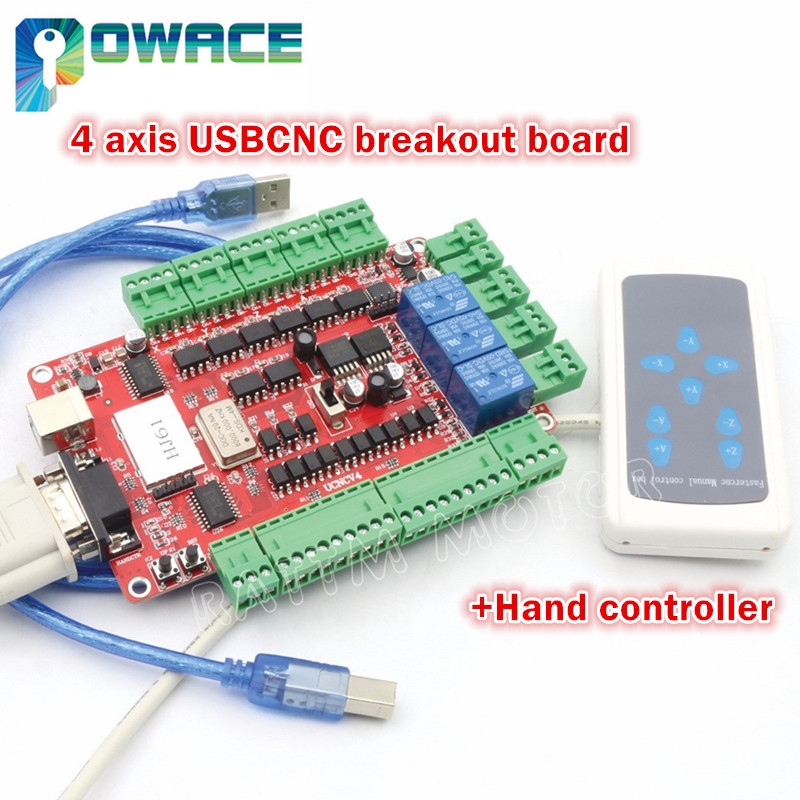
Check the listing for details. 4 Axis USBCNC Breakout Board Interface Controller+Hand Controller for CNC Router. Color: Red, Condition: New. Listed at 59.00 USD. 1 x 4 axis USBCNC breakout board1 x Hand controller 1 x USB CableCD include with English user manual and software and register code The interface board is based on USBCNC MK1 in our CD disk of parcel, cannot use other versions of the software and function 1. Products brief introduction USBCNCV4.0 is a high performance motion controller which based on PC software USBCNC control, the system can complete the conversion from G code to connect stepper motor’s driver motion control signal without requiring any additional hardware and software. This control card is compatible with most stepper driver and servo driver,it is a perfect controller that instead of parallel Mach3 interface board. 2. Computer system requirement Minimum configuration:1) CPU:1GHz2) Memory: 512MB3) 500MB free disk space4) DIRECTX9 graphics device with WDDM 1.0 or higher driver5) USB 2.0 interface6) Net FRAMEWORK 3.5SP1 The recommended configuration:1) CPU:2GHz dikaryon2) Memory: 2GB;3) 1G free disk space4) DIRECTX9 graphics device with WDDM 1.0 or higher driver5) USB 2.0 interface6) Net FRAMEWORK 3.5SP1 3.Production appearance and size1. After the revision,V4 version using the red PCB board, PCB size is 135.3*82.5mm.;2. The front of the narrow edge placed with USB communication interface and DB9 hand control interface for the convenience of customers drawn from the case panel directly;3. The back-end of narrow edge is power input and output interface and 3 relay output interface; relay is strong interference source, relay away from the design of main control chip, it is conducive to the stability of the board;4. One of the two wide sides is stepper motor and principal axiscontrol signal output;5. The another side of two wide sides is the emergency stop, manual speed input, limiting input interface; one side for the input, another side output connection mode is simple and convenient;6. 5V and 12V power module compact independence, security, stability;7. External ensure the stability of the system work effectively with crystal active and main control chip shield;8. The software is USBCNC,not mach3,pls note!9.Does not have slave function. 4.Detailed functional introductionA. Card input voltage: 15~36V;B. Limit port working voltage: 12V;C. Stepper motor control signal output voltage: 5V;D. External power supply voltage: 12V;Note: marked 15~36VDC is input interface, marked 12V is output interface, can not wiring wrong. 5.Function and definition of each module A) USB interface, connect to the computer USB port through this interface,you can use the software usbcnc to control this board, this USB interface is the square B interface,please use USB2.0 connection cable which with shielding and magnetic and not to exceed 2 meters in length. B) Hand control box interface, external hand control box can use this interface to access the system, the interface is standard DB9 form, its definition as shown in the following table. Table 4-1 Hand control interface definitionInterface serial number12345Interface definitionCommon portA axis corotationZ axis downY axis forwardX axis left moveInterface serial number 6789Interface definition A axis corotationZ axis upY axis backX axis right move C) Power indicator, as shown in figure the above D10 indicator is the front-end USB power indicator, this light lit up after USB port connection with computer , D2 in below is the back -end power indicator light, this light also will lit up when board card work power access with it. D) Board card firmware upgrade button UP and reset button RST, firmware has been updated, so upgrade button don’t need to use, reset button be used when need to restart due to the board fault. E) Manual speed control interface,wiring connection mode as shown in the following figure . F) Limit input interface. Limit interface definitions are listed in the following tableTable 4-2 Limit interface definitionInterface serial number12VMIX12VMAX12VInterface definitionSwitch common portX lower limitSwitch common portX upper limitSwitch common portInterface serial number MIY12VMAYGND Interface definitionY lower limitSwitch common portY upper limitGND Interface serial number 12VMIZ12VMAZ12VInterface definitionSwitch common portZ lower limitSwitch common portZ upper limitSwitch common portInterface serial number MIA12VMAAGND Interface definitionA lower limitSwitch common portA upper limitGND Limit switch connection as shown in figure 1-8~ figure 1-10 G) Spindle control selector switch, as shown in Figure 1-6, the switch shift up to the S1 position for the spindle speed control ; switching switch position On below for output control MIST relay . H) External pause and reset interface; the 2 feet marked PAUSE connect suspend switch, 2 feet marked RESET connection reset switch. I) Software MIST control relay output, software settings output marked 3, defined from top to bottom, 3 feet is NC, NO, COM. J) Software FLOOD control relay output ,output marked 2 in the software settings , defined from top to bottom, 3 feet is NC, NO, COM. K) Software SPINDLE control relay output , output marked 1 in the software settings , defined from top to bottom, 3 feet is NC, NO, COM. L) Board working power input, levels above negative below as the board signed, please pay attention to input DC 15~36V, overvoltage or reverse connection will damage the board. M) 12V output interface. as the board marked, GND is -, 12V is +. N) Spindle control output interface: definitions turn for GND DIR PWM2 12V, respectively is ground,direction signal output, spindle 0~10V speed control signal output, 12V output. O) A axis stepper motor control signal output, the definition is:CK+\CK-\DIR+\DIR-,respectively is impulsion positive, impulsion negative, direction positive, direction negative, the board using common anode connection method, so CK+ and DIR+ linked together to contact to the 5V on the board, this board does not support the common cathode connection method, the specific wiring methods refer to figure 1-11. This board does not contain the enable control, now most of driver in the market should not connect with the EN signal and directly work regularly by default . P) Z axis stepper motor control signal output, the definition is CK+\CK-\DIR+\DIR-, respectively for pulse positive, pulse negative, direction positive , direction negative, the board using anode common connection method, so CK+ and DIR+ linked together connect to the 5V on the board,this board does not support the common cathode connection method. Q) Y axis stepper motor control signal output, the definition is CK+\CK-\DIR+\DIR-,respectively for pulse positive, pulse negative, direction positive , direction negative, the board using anode common connection method, so CK+ and DIR+ linked together connect to the 5V on the board,this board does not support the common cathode connection method. R)X axis stepper motor control signal output, the definition is CK+\CK-\DIR+\DIR-,respectively for pulse positive, pulse negative, direction positive , direction negative, the board using anode common connection method, so CK+ and DIR+ linked together connect to the 5V on the board,this board does not support the common cathode connection method. Shipping======================================================================Please open the package and check if there are some damages before sign, if there are some damages , please do not sign and contact us immediately.We ship to worldwide,but if your country’s custom is strict, please contact us before you bid to check detail and confirmed. Payment======================================================================Import duties, taxes and charges are not included in the item price or shipping charges. These charges are the buyer responsibility.Payment must be made within 48hours of the auction end time.We accept paypal payment,all payment must be confirmed(shipping and billing address must match and correct) Problem & Feedback======================================================================Please give us the opportunityto resolve any problem when you have,we concern your problem and we will try our best to resolve it.We are a new member in ebay now,and need understand both of sides.Pls email us before you want to leave any negative feedback. Refund======================================================================Any reason required for all refund. Item must be in it's original condition and no physical damage,buyer responsible for all shipping cost.When you have the parcel,and not satisfied the goods or it is other problem like as broken,pls tell us the detail reason and provide the photos. Contact us======================================================================Welcome worldwide customer inquire and questions,we will try to do our best to feedback customer’s email within 1-2 business days,if not pls check the mail box again.Customer’s satisfaction is very important to us.
You may also like