| Restocking Fee | No |
|---|---|
| Return shipping will be paid by | Buyer |
| All returns accepted | Returns Accepted |
| Item must be returned within | 60 Days |
| Refund will be given as | Money back or replacement (buyer's choice) |
| Brand | Hantek |
| Channel | 8 |
| Country/Region of Manufacture | China |
| Custom Bundle | No |
| Digital Oscilloscope Resolution | 12-bit |
| Features | HT201 300V 20:1 Passive Attenuator |
| Modified Item | No |
| MPN | Hantek1008C |
| Non-Domestic Product | No |
| Number of Channels | 8 |
| Oscilloscope Type | Digital Storage Oscilloscope (DSO) |
| Sample rate | 2.4MSa/s |
| Type | Digital Storage Oscilloscope (DSO) |
| Unit Type | kg |
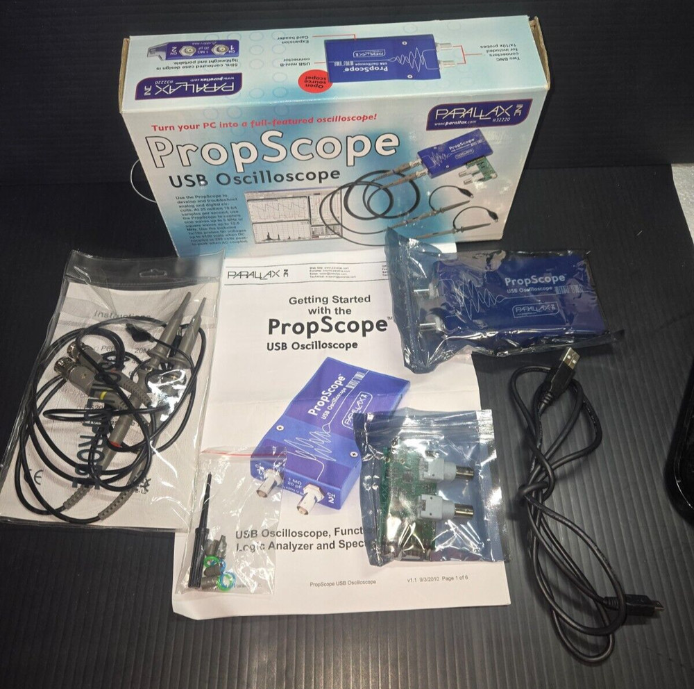
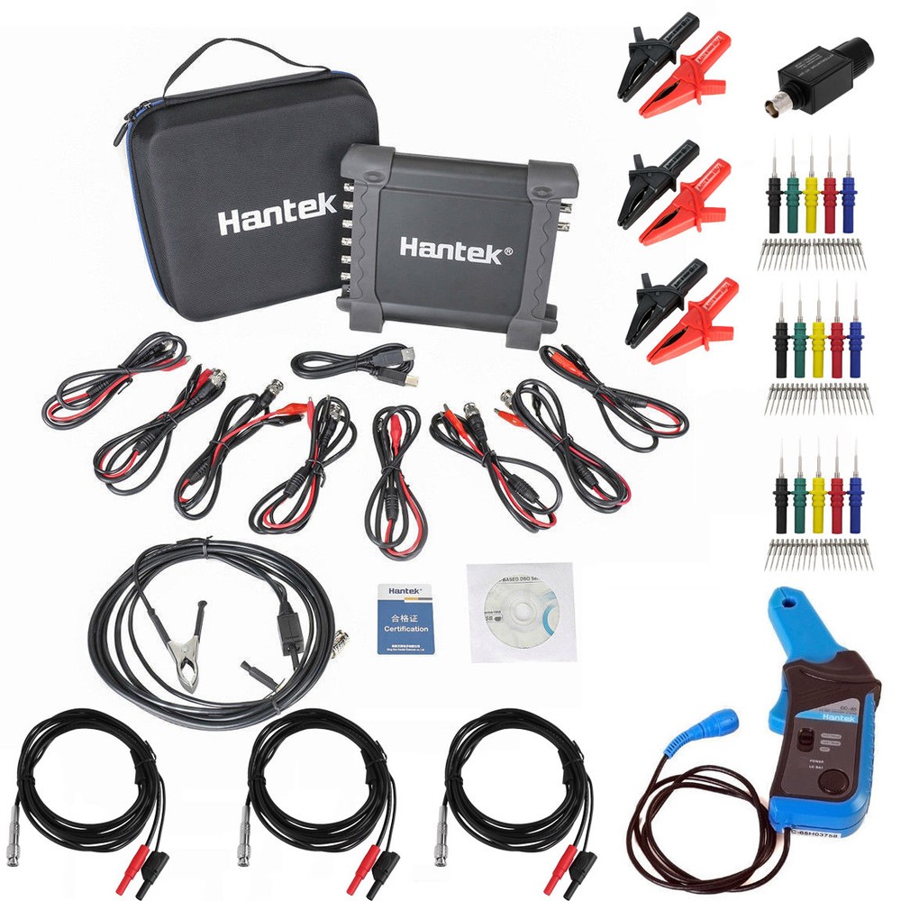
Check the listing for details. CC65 + Head + 1008C 8CH USB Auto Scope/DAQ/8CH Program Generator Oscilloscope. Condition: New. Listed at 246.99 USD. Package includes:1008C 8CH Auto Scope/DAQ/8CH Programmable Generator(Main body)*1HT30A Hantek BNC to Dual Banana Head Test Line*3CC-65A AC/DC 20KHz current clamp *1HT201 300V 20:1 Passive Attenuator *1Secondary ignition probe(HT25)*1Back pinning probe *3 sets(5pcs)Crocodile probe/cable*8HT18A Alligator Clip*3Bag(see picture)*1User manual*1USB cable*1CD(driver)*1 Features:8 channels oscilloscope for vehicle testing. Over 70 types of automotive diagnostic function (Ignition/Sensor/Bus detection/Performe/Starter and charging circuits etc.).Video Help Function, provides the video help of diagnostic which can be watching online,The diagnostic result can be generated diagnostic report., printed or taken screenshot by pushing one key, many methods to save the data.Supported to record waveform for a long time. It can simulate camshaft and crankshaft signal.Transmit signals through USB 2.0 interface plug and play, and no need extra power supply;Function Selection There are three functions of vehicle diagnosis, oscilloscope and signal generator, including 78 types of vehicle diagnosis function. One Button Screenshot Save the current waveform and generate pictures. Storage location is optional and easy to find.Quick Guide Callout the quick guide column with one button. There are special vedio guide for each vehicle diagnosis function, including wiring method, adjustment method, reference waveform etc. And it is supported to be checked through scanning the QR code. Reference Waveform There are 78 types of standard reference waveform inside and can be callout or close with one button. It is convenient to be compared.Measurement Method 20 types of automatic measurement method which can be callout or close with one button. It is convenient and visual to read out the result.Print The result can be printed with one button and generate diagnosis report which is easy to be saved and recorded.REF Comparison Waveform The user can save the waveform as REF format and callout it again when you need to compare the two waveforms catched in different time.Data Storage The diagnosis result can be saved as the format of txt, csv, rfc, xls, doc, jpg and etc. It is convenient to be checked and compared later.8CH Vehicle Diagnosis 8CH signal can be measured simultaneously. The measurement voltage of each channel can be adjusted independently. You can choose to open or close each channel.Waveform Record Support to record and replay the waveform. The waveform can be save into the computer hard disk and easy to read. There is no limit to the record time which can long-time measure and record the waveform for troubleshooting.Multilanguage Support Support the display surface in Chinese, English, German language, and it can be switched freely.Cursor Measurement Support 4 types of cursor measurement mode -cross,track, horizontal, and vertical.It's easy to read out the time and voltage of irregular signal. Color and Lightness The background color is optional as user's preference. And the lightness of waveform and gridding is settable.Easy to Install Software Install the PC software and start to use without any other drivers. Support WIN XP/7/8/10. USB Communication USB2.0 power supply + communication interface, plug and play, and support hot plugging.Signal Generator Signal generator function, can simulate crankshaft and camshaft signal. Vehicle Diagnostic FunctionIgnitionPrimary Ignition (Voltage)Primary Ignition(current)Primary Ignition(Voltage& Current)Primary Ignition (Crankshaft Senser)Primary Ignition&SecondaryIgnitionSecondarySecondary Ignition Distributor Type (Plug Lead)Secondary Ignition Distributor Type (King Lead)Secondary DIS (Positive-fired)Secondary DIS or CPC (Negative-fired))Secondary Coil Output DiagnosisSecondary Ignition&Primary IgnitionSensorsAir Flow MeterAir Flow Meter (Hot Wire)Air Flow Meter (Air Vane)Air FlowSensor (BOSCH Diesel)Air Intake PressureSensor (BOSCH Diesel)CamshaftCamshaft (Inductive)Camshaft (AC Excited)Camshaft (Hall Effect)Camshaft (BOSCH Common Rail Diesel)CrankshaftCrankshaft Inductive RunningCrankshaft Inductive CrankingCrankshaft Hall EffectCrankshaft Sensor &Primary IgnitionDistributorDistributor Pick-up (Hall Effect)Distributor Inductive Pick-up CrankingDistributor Inductive Pick-up RunningLambda SensorsLambda Sensor TitaniaLambda Sensor ZirconiaLambda Sensor Zirconia Pre & Post catThrottle PositionThrottle Position PotentiometerThrottle Position SwitchThrottle Pedal Switch (Bosch Diesel)ABS Digital Speed SensorABS Analog Speed SensorCoolant Temperature (5V)Coolant Temperature (GM/Vauxhall SimtecCrash SensorMAP AnalogMAP DigitalHall Effect Road Speed SensorAccelerator Pedal (Bosch Diesel)Bus DiagnosisCAN BusCAN Bus Data ViewCAN Bus Signal IntegrityCAN Bus LH Long CaptureLIN BusLIN BusEnginePetrolSingle-point Injector (Voltage)Single-point Injector (Current)Multi-point Injector (Voltage)Multi-point Injector (Current)Injector Voltage & CurrentInjector Current & Primary IgnitionDieselCommon Rail Diesel (Current)Injector Bosch CDi 3 (Current)Injector Bosch Diesel (Idling)Injector Bosch Diesel (Accelerating) Diesel Glow PlugsElectronic Fuel PumpCarbon Canister Solenoid ValveERG Recirculation Solenoid ValveStepper Motor Example 1Stepper Motor Example 2Idle Speed Control Valve (Rotary)Idle Speed Control Valve (Electromagmetic)Throttle Servomotor (Idling)Throttle Servomotor (Accelerating)Bosch CDi3 Quantity Control ValveBosch CDi3 Pressure Regulator ValveVariable-Speed Cooling Fan OnVariable-Speed Cooling Fan OffVariable Camshaft Valve TimingStartup & ChargeCharging CircuitsCharging Circuits Current/VoltageCharging Circuits Current/Voltage Starting 24VCharging Circuits Current/Voltage Idling 24VCharging Circuits Alternator AC Ripple/Diode Diagnosis Relative Compression PetrolRelative Compression DieselStarting Voltage DropGeneral OscilloscopeModel Hantek1008CAnalog Channel8Input ImpedanceResistance: 1MΩ Input Sensitivity10mV/div to 5V/divInput CouplingDCResolution12 bitsMemory Depth4KMax. Input400V (DC+AC Peak)Real-Time Sampling Rate2.4MSa/sTime BaseRange1ns/div to 20000s/div(1-2-5sequences)Time Base Precision±50ppmTrigger SourceCH1, CH2,CH3,CH4, CH5, CH6,CH7,CH8Trigger ModeEdgeX-Axis InputCH1Y-Axis InputCH2Voltage MeasurementVpp, Vamp, Vmax, Vmin, Vtop, Vmid, Vbase,Vavg, Vrms, Vcrms, Preshoot, OvershootTime MeasurementFrequency, Period, Rise Time, Fall Time, Positive Width, Negative Width, Duty CycleCursors MeasurementHorizontal ,Vertical, Track, Auto Measure ModesWaveform Signal Process+,- , x,÷, FFT, InvertVoltage Range10mV to 5V/div @ x 1 probe 100mV to 50V/div @ x 10 probe10V to 5000V/div @ x 1000 probe100V to 50000V/div @ x 10000 probe200mV to 100V/div @ 20:1Current Range100mA to50.0A/div @ CC65(20A)1000mA to500.0A/div @ CC65(65A)1A to100.0A/div @ CC650(60A)1A to200.0A/div @CC1100(100A)10A to2000.0A/div @CC1100(1100A)FFTRectangular, Hanning, Hamming, Blackman WindowMathAddition, subtraction, multiplication, divisionInterfaceUSB 2.0(Full Speed)PowerNo need extra power supplySize190 x 167 x 35 (mm)Weight0.63kgHigh pressure ignition probe1Programmablesignal generatorChannel8CHOutput LevelLVTTLFrequency Range0-250kHz 3. Connection method: 1 . Connect the BNC end of the A test line to the CH1 channel of the oscilloscope, the positive pole is inserted into the signal line terminal of the camshaft sensor through the probe, and the negative pole is grounded with the alligator clip;2 . Connect the BNC end of the B test line to the CH2 channel of the oscilloscope, insert the positive pole through the probe into the positive terminal of the crank signal line, and ground the negative crocodile clip; 3. Turn on the CC65 current clamp power supply, put it in the 1mv/10ma file, clamp the positive electrode of the fuel injector and connect it to the oscilloscope CH3;4. Connect the HT30 test line BNC end to the HT201 attenuator and connect it to the oscilloscope channel CH4. The probe positive connection probe detects the ignition coil ground terminal. First Diagnosis: Intake manifold vacuum & ignition, Petrol fumes adjusting valve vacuum & ignition, Idle exhaust ignition, Starting exhaust ignition Ignition: primary and secondary Sensor: Air Flow Meter, Camshaft, Crankshaft, Distributor, Lambda sensor, Throttle position Bus Diagnosis: CAN bus data examine, CAN bus signal integrity, CAN bus LH long time acquisition, LIN bus Performer: Petrol/Diesel Starter and charging circuits
You may also like