| All returns accepted | ReturnsNotAccepted |
|---|---|
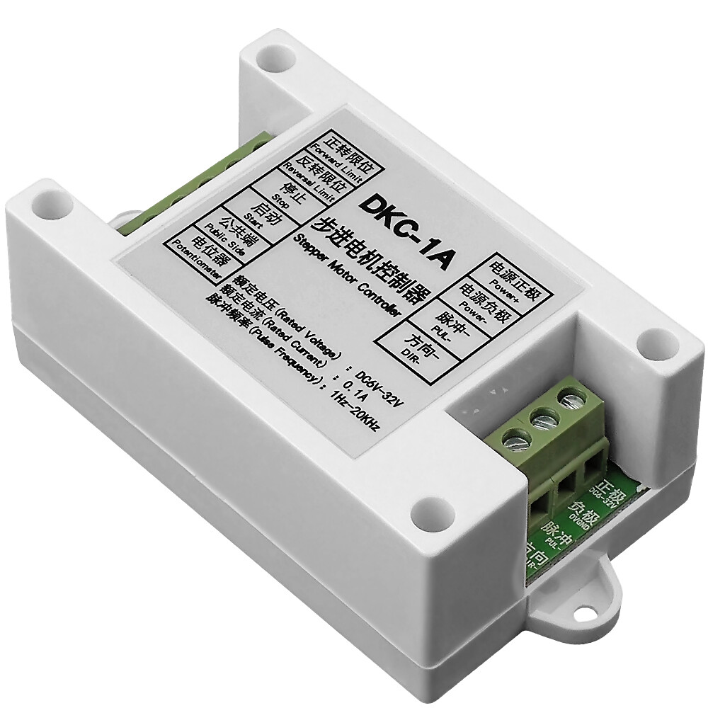
| Model | DKC-1A |
| Country/Region of Manufacture | China |
| Input Voltage | 5-32 V |
| MPN | Does Not Apply |
| Brand | DC |
Check the listing for details. DC 5-32V Stepper Motor Controller Governer CC/CW Control Pulse Servo Generator. Condition: New. Listed at 10.99 USD. DC 5-32V Stepper Motor Controller Governer CC/CW Control Pulse Servo Generator Description DKC-1A is an economical stepping motor controller. It uses an imported and high speed intelligent chip, its software inherits the stability, reliability and strong anti-interference of the original version DKC-1, so it is applicable to all kinds of harsh environment in any factory site. At the same time, some functions are added to make the controller more practical and convenient, which is suitable for the round-trip motion control, limited function control, speed control and the like of sensors. Parameters:1. Voltage Input: DC5V - 32V 2. Multiple Protection Functions: anti-connection protection, over-voltage protection, over-current protection 3. Speed Regulation Performance: intelligent and automatic switch between on-board speed regulation and external speed regulation 4. Acceleration and Deceleration: used S- acceleration, with function of immediate stopping 5. Output Frequency: up to 20KHz 6. Input and Output: all input is optocoupler isolation, while output the negative pulse. The low level signal is valid.Function SettingOperation mode: (dip switch, 1-up, 0-down) Automatic Round-trip ModeSingle Trigger ModeSingle Round Trip ModeJog ModeS10011S20101NOTE: 1. The control signal is 0-24V. The signal is valid at the falling edge. The trigger signal must be over 2.5US.2. The on-board potentiometer and the external potentiometer are automatically switched. If the interface of the external potentiometer is suspended, the on-board potentiometer will regulate the speed. If the external potentiometer (less than or equal to 10K) is connected, the control board will automatically switch to the external potentiometer to adjust the speed. 3. Operation setting switch and the on-board speed-regulating potentiometer are inside the controller, please open the case to set them. Functions Automatic Round-Trip Mode: After the controller is triggered and started, (COM and K4 connected), the motor will automatically move back and forth between the FWD limit and the REV limit until the input of the trigger is stopped.Single Trigger Mode: After the controller is triggered and started, the motor is in forward rotation until it touches the FWD limit to stop. It will be in reversal rotation if the controller is triggered and started again and will stop when it touches the REV limit. Start the motor and it will be in forward rotation again on and on.Single Round Trip Mode: After the controller is triggered and started, the motor is in forward rotation until it touches the FWD limit to stop. Then it automatically starts to reverse and won’t stop until it touches the REV limit.Jog Mode: When COM and K4 connected, the motor will be in forward rotation. When COM and K4 are disconnected, the motor will stop. When COM and K3 are connected, the motor will be in reversal rotation. When COM and K3 disconnected, the motor will stop Wiring and Other Instructions1. Connection to the Driver As a universal stepping motor, the controller serves motor controller. The general step motor drivers which serve motor drivers can be controlled and used for matching, regardless of the size of the motorsWiring and Other InstructionsEN=ENA=PREE Enable; PUL=PULS=CLK Pulse; DIR=CW=CCW Direction The controller uses common-anode connection:Driver “PUL+” and “DIR+” connects to VDD +24V Controller “PUL-” connects to driver Pulse input port (PUL-、PULS-、CLK-) Driver “DIR-” connects to driver Direction input (DIR-、CW-、CWW-) “En+” and “En-” are usually disconnected2. Limit Switch and Button Switch Suited to use mechanical switch, button switch, limit switch, foot switch which are with normally open two-foots. One foot connects the COM, and the other is attached to the start port, stop port, forward and reverse limit ports correspondingly.Suited to use optoelectronic switches, proximity switches, Hall switches and other electronic switches which use DC24V three-wire-often-open NPN. Two of the lines are power lines, which are directly connected to the controller's power supply. Another line is a signal line directly connected to the start port, stop port, forward and reverse limit ports and other input ports correspondingly3. External Potentiometer The external speed regulating potentiometer needs to be 10K-value resistance or less. The connection of the external potentiometer only demands its middle foot to be connected to COM and the foot at the other side the external speed controller input port4. Other InstructionsWhen debugging the controller for the first time, the controller, the driver, the motor, and the power supply must be connected properly. Then a small wire should be connected to the common port for debugging. After the power is turned on, the other port of the wire is used to connect K4 and K3 port and the like to imitate the switch functions. After making sure that every function does work by the debugging, connect each switch, the external potentiometer and other accessories step by step Package Included:1 * stepper motor controller (with Manual)
You may also like